Making sure you get the best force torque sensing solution for your application can be complicated. Selecting the best Force Torque Sensor is dependent on the specific application.
Understanding the types of features, specifications, and software needed can be tricky. This comprehensive guide will make the process of selecting the best force torque sensor for your application a little easier.
At Bota Systems, when we pair a sensor with an application, we focus on the most important specifications, which commonly include range, noise-free resolution, sampling rate, signal type, and size.
Force and Torque Range
We define the range as how much force or torque a sensor is capable of measuring starting at 0 N.
For example:
A scale may have a limited weight capacity of 180 Kg, and if a 200 Kg person steps on the scale, it will probably still register their weight but will output 180 Kg instead of the accurate weight of 200 Kg because it has a range limitation of the scale is 0-180 Kg.
For force-sensing applications and measuring, the sensor’s range needs to be greater than or equal to the maximum force to be applied, measured, and controlled.
The FT sensor’s specification sheets will usually define a range for single-axis loadings. Some specification sheets will illustrate with a 2D graph all the combinations that can be achieved in multiaxial loadings.
All combinations that fall inside the graph should be accurate. Combinations that fall outside of the graph are known as saturated signals. These saturated signals will lead to inaccurate force measurements, similar to our example of a 200 Kg person using a scale with a limited weight capacity of 180 Kg.
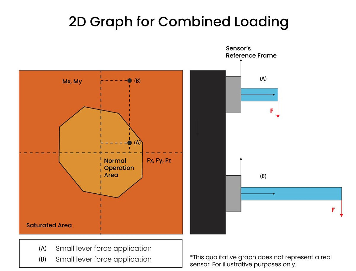
Selecting a sensor that is capable of measuring the maximum force to be applied is essential.
Noise Free Resolution
The easiest way to select a sensor is by choosing a sensor that can detect the minimum force to be measured from the application.
We define minimum measurable force as the minimum amount of force a sensor can measure and the incremental changes in measurements it can sense. At Bota Systems, we call this noise-free resolution.
Knowing the minimum measurable force needed for your application and directly comparing it with the noise-free resolution of the sensor is the best way to select a sensor with proper sensitivity. The noise-free resolution should be smaller than or equal to the minimum force measured.
The noise-free resolution of Bota Systems’ sensors is defined as the 6σ of a signal over 1 second of measurements in stable environmental conditions.
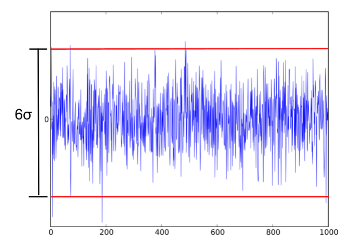
Note: Noise-free resolution is equivalent to peak-to-peak noise.
One can use this application note from Analog Devices to calculate the effective resolution or other signal characteristics associated with noise for more sophisticated signal processing.
Minimum Sampling Frequency
The sampling frequency refers to the amount of data a sensor collects per unit of time (typically seconds).
These data packets are delivered to the sensor’s output port (Serial or EtherCAT) at the same rate and with minimal latency, which will be discussed later. Sampling frequency is measured in samples per second, and sometimes expressed in hertz (Hz).
For example:
When we record a video on our smartphones, we are essentially capturing a series of consecutive images displayed one after another, taken by the phone’s vision sensor.
The number of images displayed per second is called the frame rate or frame frequency. Frame rate is typically expressed in frames per second (fps), while frame frequency is expressed in hertz (Hz). The quality of video playback on our screens depends on how many frames are shown per second.
The higher the fps, the smoother and more natural the video appears. At frame frequencies below 30 Hz, the human eye can perceive flickering, and some visual information may be lost. Therefore, it is generally recommended to record or play back video at more than 30 Hz to ensure smoother visuals and preserve detail that the human eye can detect.
A similar concept applies to force sensors. Instead of frames per second, we use samples per second, and instead of a video’s three-dimensional content, the force signal is typically one-dimensional, representing force (in newtons, N).
For instance, if you have a sensor with a 1000 Hz sampling rate and you press on it, the sensor collects one sample every 1 millisecond.
The sampling rate is crucial because it determines how accurately the sensor can reconstruct the force signal. The faster a robot’s processor receives this information, the quicker it can respond and adjust the applied force.
The required bandwidth of the overall system depends on the application’s dynamics. For example, if the task involves controlling impact forces between two low-mass metal components, even a 1000 Hz sampling rate might not be sufficient to detect sharp spikes during contact.
However, most industrial robotic applications do not require such high fidelity, and sampling rates between 200 and 500 Hz are typically adequate.
In advanced robotics, such as high-speed quadrupedal locomotion, ultra-high sampling frequencies may be necessary. This is because the robot’s feet may contact the ground for less than 20 milliseconds, requiring the controller to analyze sensor data, process it, and respond in a very short time.
Here is a list of sampling frequency ranges for common force-sensing applications:
Wrist force-torque sensor- 50 to 200 Hz is usually enough due to slow controllers
In hand manipulation- 50 to 200 Hz
Aerodynamic force measurements- 5 to 100 Hz
Force measurement for surgical robots- 100 to 1000 Hz
Bipedal locomotion- 400 to 1000 Hz
Monitoring and post-processing- The higher, the better. The advantage of post-processing is that the signal can be denoised after recording
Hand guidance- 10 to 200 Hz
Polishing- 10 to 500 Hz
Grinding- 50 to 500 Hz
Assembly of solid high stiffness components like PCBs– 200 to 1000 Hz
Signal Type
To better understand signal types concerning force torque sensor selection, you may want to familiarize yourself with signals.
Categorized by their output, the two main types of signals, and force torque sensors, are analog and digital.
Analog Force Torque Sensors
Analog force torque sensors require extensive programming, external electronics, and a connection to a network protocol, making this force sensing solution more expensive, time-consuming, and complex.
However, the advantage of using an analog sensor is that it can operate under extreme temperatures, and why they are still used in applications today.
Applications that need analog sensors are those where the environmental conditions, such as temperature, humidity, pressure, are extreme.
Digital Force Torque Sensors
Digital force torque sensors have the advantage of EMI immunity, no induced or parasitic load from cables to affect their signal, quicker integration time, lower complexity, and overall less expensive.
Also, due to embedded electronics and firmware that take care of the necessary calculations, the digital sensors come with certain advantages over the analog ones:
Low and predictable noise levels
Ready to use data in N and Nm
Low drift from temperature fluctuations because it is calculated in the device
No signal aliasing. A digital sensor either works or does not
No additional components or external electronics are required when compared to analog sensors
With new technology and innovation, digital sensors can operate in the same extreme temperatures and environments as analog sensors.
If a digital sensor can work with your application, we recommend selecting one because analog sensors are more complex and prone to measurement errors if you are not an expert.
Force Torque Sensor Size
When it comes to sensor size, the most important dimensions are the diameter and the height of the transducer. When selecting a sensor for robotic manipulation, consider a shorter sensor since taller sensors reduce the effective payload of a robot.
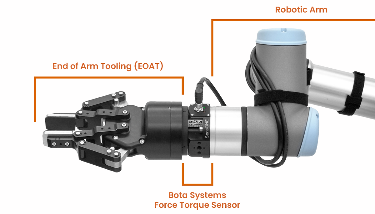
Bota Systems sensors are designed to be compact and eliminate external adapters needed to minimize the offset from any EOAT.
The picture below is a Universal Robot integrated with a SensONE force torque sensor and EOAT gripper and showcases how simple force sensing can be with Bota Systems.
Conclusion
Understanding the specifications your applications requires for range, noise free resolution, sampling rate, signal type, and size will allow you to use the process of elimination and narrow down your search for your best force sensing solution.
If your application has unique demands or you’re still unsure which sensor best fits your needs, we’re here to help. Contact Botasys today—our team of experts will guide you in selecting the most suitable force torque sensor tailored to your application.