
Frequently Asked Questions
Ready to add force-sensing to your robotic system, but still have questions? Check out our most frequently asked questions to learn more, or ask an engineer.
Browse our FT Sensor topics below to find what you are looking for.
How does a force torque sensor work?
A force torque sensor is an electronic device that converts the physical quantity of force and torque to a signal that can then be read by a human and/or a robot.
An object can experience force and/or torque from various sources. In continuum mechanics, bodies are considered deformable. When a force is applied, deformation takes place. Deformation is directly related to the force applied. One way to measure deformation is by attaching a film of variable electrical resistance to the deformed body surface by glue or other methods to share the same deformation. The resistance changes when the body elongates or compresses, due to force applied. This change is then captured by an Analog to Digital Converter (ADC) and is recorded as a digital counter. Then, it is processed by a microcontroller and sent via the communication channel of the system’s network for further processing.
A simplified example of processing:
When a force of 100 N is applied, the digital counter records a change of 1000 counts. The most simple sensor design is to have a linear relation between force and the change of counts. In this case the force is directly proportional to the change of counts by a factor of 10. If a change of 1500 is recorded then a force of 1500/10 = 150 N is applied. It is safe to say that if a change recorded is divided by 10 we can simply calculate the value of force applied. This is what happens on a digital weight scale. The only difference is that weight scales show the mass of an object by dividing force by the gravity acceleration of a specific location (usually the calibration location).
For a 6-axis force torque sensor, three force and three torque components of the force/torque vector are applied and six signals from six different variable resistances can be recorded. Each one of these components affects, to a greater or lesser degree, the individual variable resistances that are located at the different spots on the sensor body. By linear combination of the six signals through an individual calibration matrix, the physical quantities of force and torque are obtained.
How do I choose a sensor?
Sensor selection is primarily dependent on the application. Each application is unique and requires a force torque sensor to have certain features, ranges, or software specifications.
Check out our blog post on how to select a force torque sensor for more details.
To get the best force torque sensing solution, we recommend contacting us and sharing your application details.
What is the first thing I should do when I receive my sensor?
Unbox the sensor carefully and read the Quick Start Guide and User Manual l before using your FT sensor.
We recommend navigating our FAQ, like you’re currently doing, to understand how our sensors work and resolve common concerns about using FT sensors.
How do I calibrate the sensor?
Bota Systems sensors come pre-calibrated with a calibration matrix saved on the device.
The only calibration required is an offset calibration that can be done externally by gathering data while the sensor is steady and no change in the dynamic state is happening. After the data is averaged, it can be subtracted from the current measurements.
Can my Bota Systems sensor become more sensitive?
Sensor sensitivity is directly related to the sampling frequency. The internal sensor filters can be utilized to increase the sensitivity.
The user manual provides a table with all available filtering options and the resulting resolution after a filter is applied.
Note: The internal filters are hardware filters optimized for a force-torque sensor signal. One can potentially run the sensor at full speed and apply one’s own filtering.
The Rokubi force-torque sensor has a range of 1200N. Is this suitable for an application that requires a lower range?
It depends on the maximum force being applied and the resolution requirements of the application.
The Rokubi sensor has 0.2N noise-free resolution on the z-axis at 1000Hz and a range of 1200N. For example, if the maximum force to be applied on the z-axis for your application is 300 N and the resolution required is more than 0.2N, then Rokubi is a sensor that can be used for your application.
What is noise-free resolution?
We define noise-free resolution as the 6 sigma (σ) of a signal. σ stands for the standard deviation of the signal. It is calculated by recording 10 sec of measurements when the sensor is in a static condition. 6σ defines the peak-to-peak range that the noise level will remain below for 99.73% of the time.
What causes signal noise, and how to reduce signal noise?
Did you know, in most robotic systems, noise is inevitable? However, noise corruption is unacceptable for applications, especially those that are safety-critical, like robotic-assisted surgery. Learn more about reducing signal noise.
Do I need any extra accessories to install the sensor into my application?
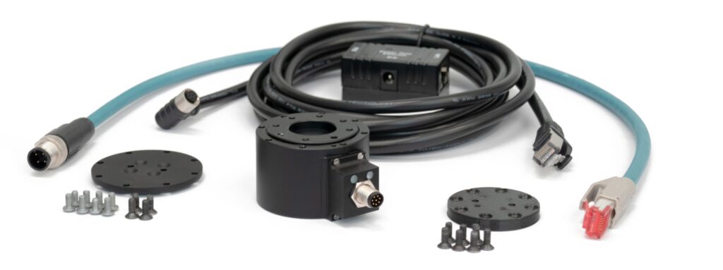
Bota Systems sensors are designed to minimize integration efforts and have the smallest footprints and integrated flanges.
Sensors include:
- All necessary wires & cables.
- Electrical adapters are NOT required. Our Serial and EtherCAT sensors come with all the necessary accessories for mounting on a USB or Ethernet port and connecting directly with a PC.
- Electronic boxes and signal amplifiers are NOT required. Bota FT sensors are integrated with all signal transformation electronics. Check out our force-sensing kits for Universal Robots and Mecademic Robots.
What is drift? And how to manage drift?
Drift is when sensors behave as if a force is being applied to the robot when it is not. If you want reliable and accurate force measurements, drift must be managed/minimized, and when managed properly, it increases a robot’s productivity.
To manage drift, you must first discover the source. This can be dependent on the type of application, type of sensor, and the environment. Depending on your drift source, you should respond with an appropriate solution. Below are types of drift sources and ways to manage drift. Check out our comprehensive guide on how to manage sensor drift for more details, or contact us to discuss solutions.
Drift Sources:
- Heat
- Mechanical creep
- Sensor design
Tips and solutions :
- Mount the sensor according to the specifications, use all screws and pins.
- Operate the sensor under stable environmental conditions, warming up a sensor before using it.
- Offset the sensor measurements from the bias regularly, or even every couple of seconds, depending on your needs.
- Stop, reset the sensor, and once stabilized, start again.
Does my force-torque sensor need an IMU?
Force torque sensors are mainly used to measure the contact forces when a robot interacts with an object. Besides contact forces, inertia forces/torques are commonly applied to the robot’s end-effector while it is moving. Gravitational forces being one of them. Even in quasi-static motion, these forces are present and are measured with the contact forces, leading to inaccurate contact force measurements.
To compensate for these additional forces, a calibrated IMU can be used to give a clear contact force signal. Furthermore, an IMU can provide other tactile information like vibrations during slippage and complement the force torque measurements. Often, IMUs are also used for state estimation and directly provide the sensor’s orientation with respect to gravity.
All our EtherCAT sensors come with an integrated IMU. Have a look at our product pages to find the model fitting your application.
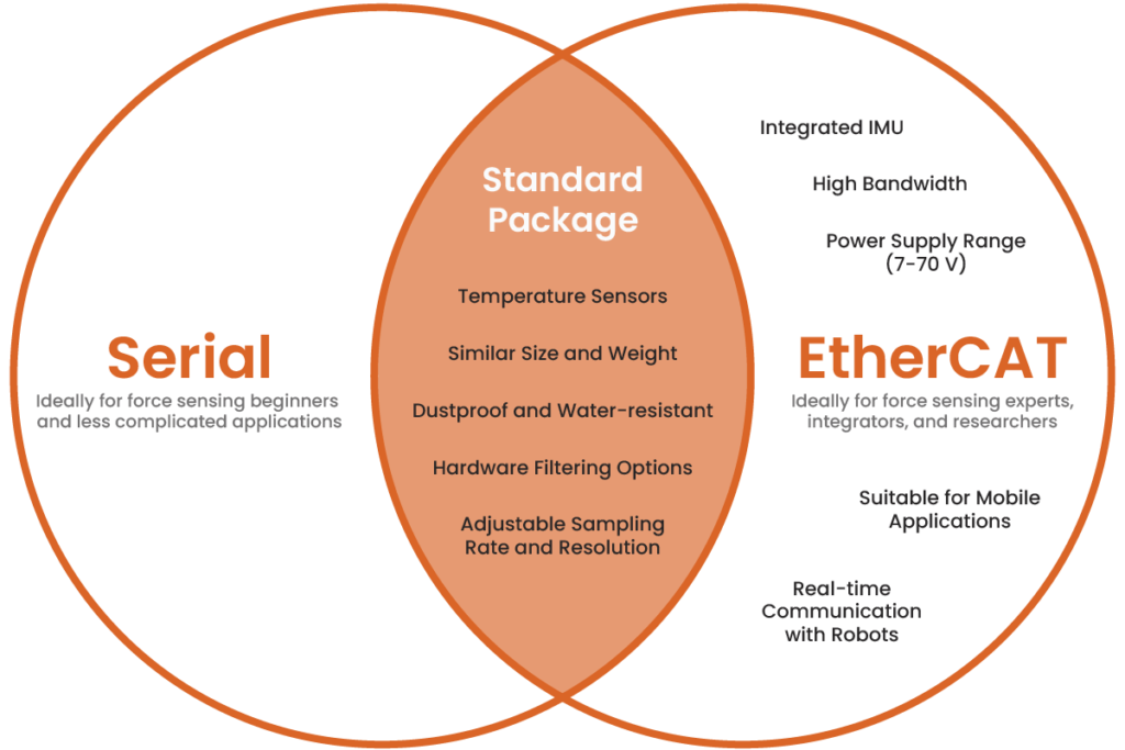
What is the difference between Serial and EtherCAT?
Serial
Our Serial devices are ideal for force-torque sensing beginners because a significant amount of documentation is available to support them, and they are easier to code.
EtherCAT
EtherCAT devices are generally more expensive and include extended features compared to their Serial counterpart. One may consider the EtherCAT version as a premium industrial sensor. EtherCAT protocol supports high bandwidth, real-time communication with robots, and can connect to a huge network of devices.
- Supports high bandwidth – can theoretically support and communicate with up to 65,000 devices.
- Supports real-time communication with robots
- A power supply range of 7 to 70 V
- Suitable for mobile applications
- Has an integrated IMU for dynamic compensation
For example, at Bota Systems and Robotic Systems Lab of ETH Zurich, we use EtherCAT for high-speed control of quadrupedal robots with up to 16 actuators, four sensors, and many other peripherals where synchronization is a critical factor to making the robot move successfully.
Because EtherCAT is powerful, it needs a lot of complex coding to parse data correctly, and this can make integration complex if not familiar with the coding process. That is why we support our devices with ready-to-use code, examples, and are continuously working on new development to facilitate integrator’s needs.
Serial & EhterCAT
Both include:
- Temperature sensors
- Hardware filtering options
- Adjustable sampling rate and resolution
- Dustproof and water-resistant
- Similar in size and weight
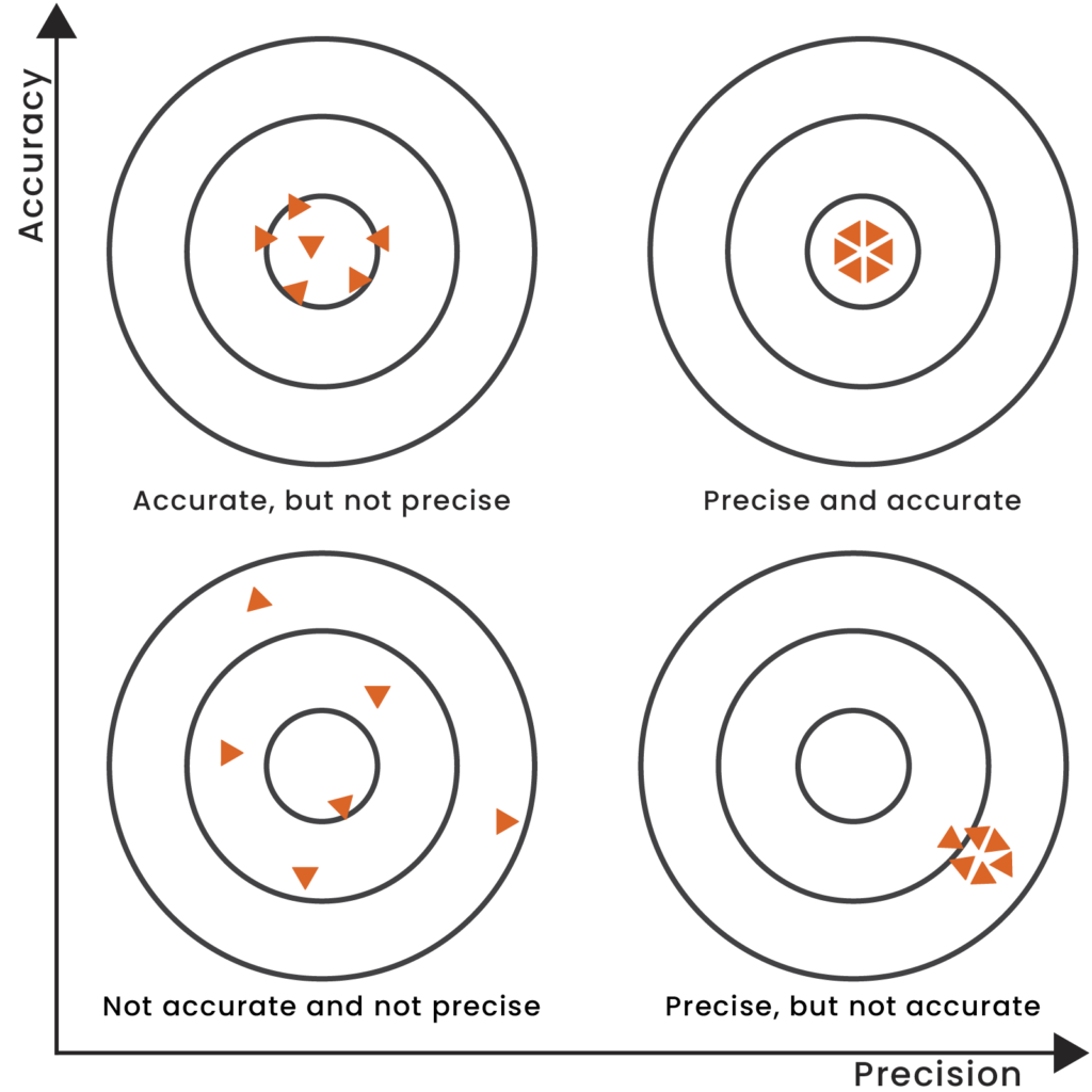
What is repeatability, and why is it important for force-control applications?
Repeatability is the ability of a sensor or system to regenerate a signal under the same loading and environmental conditions. For robotic force-control production applications, the ability to replicate a product tens and thousands of times is important for the business to operate smoothly.
For example, a polished orthopedic implant should be consistent in surface texture, so that the finished product is both compliant and safe for the patient. For surface consistency, a robot performing the polishing process needs to apply the same force on thousands of units. For this to be possible, a sensor with high repeatability in measurements is necessary.
Note: Repeatability (precision) and accuracy are two different things. Accuracy is a metric that can be calibrated and calculated, but repeatability is connected to the sensor’s design and manufacturing.
How do you calculate noise-free resolution?
At Bota Systems, we calculate a sensor’s noise-free resolution, the peak-to-peak values of the signal, as a multiple of the standard deviation σ. We then calculate the standard deviation by recording one second of continuous measurements in a stable environment when the sensor is not loaded. Assuming the noise signal follows a normal distribution.
For example, 6σ means the resolution will have a probability to exceed nominal peak-to-peak values for 0.27% of the time.
Why do I not see data when I connect a serial sensor?
There are several reasons that can cause this behavior:
Sensor Type: Make sure that the sensor has a serial interface, see the product number that is written around the connector of the sensor, it needs to have “SER” in the 3rd part, e.g. BFT-SENS-SER-M8 or BFT-MIPS-SER-CG
Serial Port: Make sure that the sensor has been connected using the supplied cabling and that the computer has recognised it as a serial port. You can check this under device Manager -> Ports (COM & LPT), there is going to be a device named USB Serial Port (COMxx). If more than one device with this name is present, unplug the USB end of the supplied cable and see which COM port is disappearing. Re-connect and save the name (e.g. COM12). You can also check using the browser application app.botasys.com and clicking connect and search for a line called USB serial Port. If more than one device with this name is present unplug the USB end of the supplied cable and see which COM port is disappearing. Re-connect and save the name (e.g. COM12). Then connect to the sensor. When you click connect, if the correct port is selected, the green led of the sensor should briefly blink green and become permanently dimmed. If unsuccessful, follow the process above to find the correct port.
Baudrate: If the application reports connected, but still no data have been shown, most probably the baudrate is incorrect. Our sensors come by default with a baudrate of 460,800 bps. If you modified the baudrate and forgot it, there is a way to recover it: Open a terminal configured with 230,400 bps and close the port, clear the terminal, and re-open the port. The first line you will receive will have a format like this : c,0,1,0,3 where the last digit (here “3”) represents the saved baudrate, please consult the manual to see to which baudrate this number corresponds and then go back to app.botasys.com and try the correct baudrate.