From silos to cobots, precision starts with microscopic strain. See how a strain gauge load cell turns that signal into millivolts and rock-steady weight.
A strain gauge load cell is an electromechanical transducer that converts force into a tiny change in electrical resistance using bonded strain gauges wired in a Wheatstone bridge.
When the elastic element strains under load, the gauges change resistance and the bridge outputs a millivolt-per-volt signal proportional to force.
Why it matters
From retail scales and batching systems to robotics and materials testing, precise force measurement underpins process quality and safety. In this guide, you’ll learn what a strain gauge load cell is, how it works, the major types, the specs that actually matter, and how to select and integrate one for reliable results.
What is a strain gauge load cell?
Strain gauge vs strain gauge load cell—these terms are related but not interchangeable:
A strain gauge is a resistive sensor whose resistance changes with mechanical strain.
A strain gauge load cell is the complete transducer: a machined elastic body with bonded strain gauges, wiring, environmental sealing, and a cable/connector—delivering a calibrated electrical signal.
Typical sensitivity is 1–3 mV/V at rated load. With a 10 V excitation, a “2 mV/V” load cell outputs ~20 mV at full scale. Most systems therefore, need a low-noise instrumentation amplifier or a high-resolution ADC to digitize that small differential signal.
Applications include bench/platform scales, hoppers and silos, tensile testers, collaborative robots, and medical devices.
Working principle
Within the working range, the elastic element follows Hooke’s law:
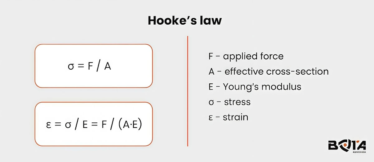
A bonded gauge converts strain to resistance change:
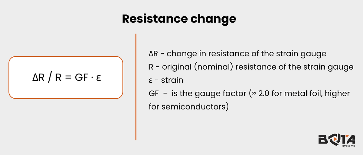
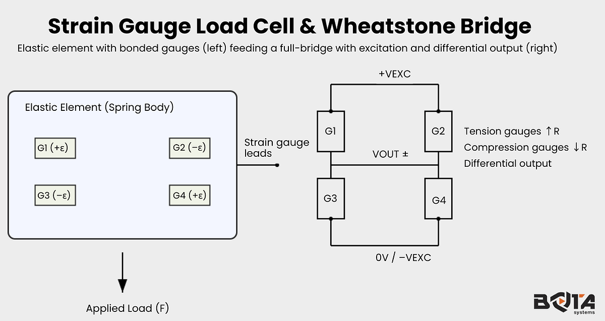
Wheatstone bridge basics
Four gauges are commonly wired in a full bridge so that tension gauges increase R while compression gauges decrease R. For small changes and ideal symmetry:
Quarter bridge (1 active gauge): Vout ≈ (GF · ε / 4) · Vexc
Half bridge (2 opposite-arm gauges): Vout ≈ (GF · ε / 2) · Vexc
Full bridge (4 active gauges): Vout ≈ (GF · ε) · Vexc
Commercial strain gauge load cells use full bridges to maximise sensitivity, cancel temperature effects, and improve common-mode rejection.
Datasheets express sensitivity directly in mV/V at rated load, so a practical rule is: Vout_FS ≈ S_(mV/V) × Vexc (e.g., 2 mV/V × 10 V = 20 mV).
Practical signal considerations
Use 4-wire cabling for short runs; 6-wire (with remote sense) for long runs or variable temperature to compensate for voltage droop
Keep leads short, shielded, and properly grounded to cut noise; route away from VFDs and high-current lines.
Choose an instrumentation amplifier/ADC with sufficient gain-bandwidth and CMRR; match ADC input range and reference stability.
Types of strain gauge load cells (form factors & use cases)
The load cell’s elastic geometry determines how force is resolved into strain. Common form factors are optimised for different mounting and load paths.
Single-point (platform) — corner-load compensated; ideal for retail/bench platforms with one cell.
S-beam (tension/compression) — versatile for hanging scales and inline force measurement.
Shear beam and double-ended shear — robust floor scales, conveyors, tank/hopper weighing.
Canister/column — high capacities with excellent overload characteristics; truck scales, silos.
Pancake/spoke — low profile, high precision; materials testing and fixtures.
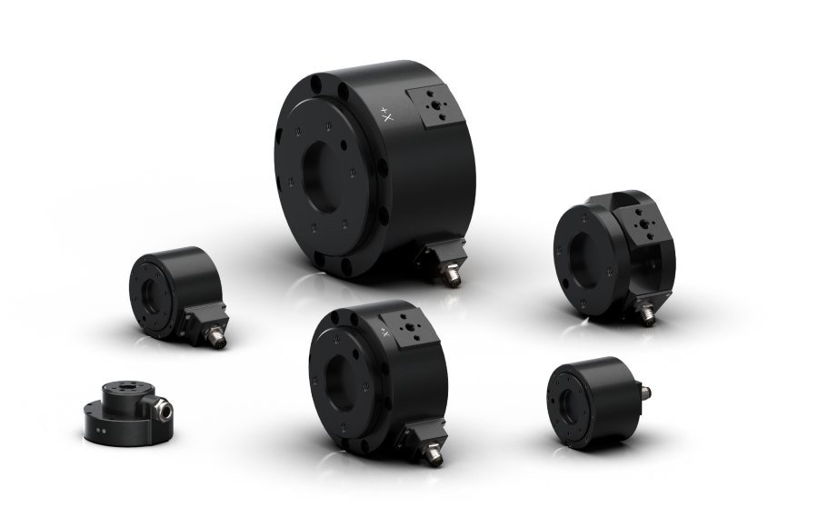
Miniature/button — tight spaces and robotics end-effectors.
Quick chooser:
|
Type |
Direction |
Typical capacity |
Typical uses |
|
Single-point |
Compression |
3–200 kg |
Benchtop/platform scales |
|
S-beam |
Tension/Compression |
25 kg–5 t |
Hanging scales, test rigs |
|
Shear beam |
Compression |
200 kg–10 t |
Floor scales, tanks |
|
Canister/column |
Compression |
5–500 t |
Silos, truck scales |
|
Pancake/spoke |
Compression |
1–100 t |
Materials testing |
|
Mini/button |
Compression |
50 N–50 kN |
Robotics, fixtures |
Types of strain gauges inside load cells
Several gauge technologies are used inside strain gauge load cells:
Bonded metal foil — stable, affordable, widely used; good temperature behaviour
Semiconductor — much higher gauge factor, more temperature-sensitive; used when signal amplitude is critical.
Thin-film (vacuum-deposited) — premium stability and repeatability for high-end transducers.
Sealing and protection — adhesives, carrier materials, and IP65–IP68 sealing impact drift and longevity.
The specs that actually matter: reading the datasheet
Capacity & overload — observe safe vs ultimate overload limits.
Accuracy terms (%FS): non-linearity, hysteresis, repeatability; and creep (zero/loaded over time).
Temperature effects: TC zero and TC span (e.g., %FS/°C).
Sensitivity (mV/V) & excitation (5–10 V typical; check maximum).
Input/Output resistance (bridge ohms) for amplifier matching and remote sense planning.
Environmental: IP rating, operating temperature, stainless vs alloy steel materials.
Legal-for-trade: OIML R60/NTEP classes for commercial weighing.
Selection & integration guide
Define the load path, size capacity with a sensible safety factor, and integrate mechanically and electrically with care.
Define the load path — tension, compression, or both; account for side loads and moments.
Capacity sizing — Capacity ≥ (Dead Load + Live Load) × Safety Factor (1.2–1.5 static; higher for shock/vibration).
Mechanical integration — use appropriate mounts (rocker columns, foot mounts), align the force vector, and trim corners in multi-cell platforms via a junction box.
Electrical integration — prefer 6-wire cells (±EXC, ±SIG, ±SENSE) for long runs/temperature variation; use shielded twisted pairs and a single-point ground; choose a matched amplifier/ADC or digital load cell.
Calibration & troubleshooting
Zero and span with traceable weights; shunt calibration for quick bridge health checks.
If readings drift: inspect mounting bolts, seals, cable nicks, moisture ingress, and temperature swings.
Bridge resistance out of spec often indicates damaged gauges or cabling.
Intermittent outputs typically trace back to loose connectors or EMI.
FAQs
Strain gauge vs load cell—what’s the difference?
A strain gauge is the resistive sensor. A load cell is the complete bridge-wired, calibrated transducer assembly that produces a usable electrical output (in mV/V) proportional to force/weight.
What output do strain gauge load cells produce?
A small differential signal specified as mV/V at rated load (e.g., 2 mV/V). With 10 V excitation, that’s ~20 mV full-scale—hence the need for a precision amplifier/ADC.
Can I use a strain gauge load cell with Arduino/PLC?
Yes—use a load-cell amplifier (instrumentation amp or dedicated ADC module). Ensure input range, filtering, and sample rate match your application.
Conclusion
A strain gauge load cell uses bonded gauges on an elastic element, wired as a Wheatstone bridge, to convert force into a precise electrical signal.
Choosing the right form factor, sizing capacity with a sensible safety factor, integrating with proper mounts and wiring (ideally 6-wire), and performing regular calibration will deliver stable, reproducible measurements in real-world conditions.
About Bota Systems
Bota Systems develops compact, high-performance multi‑axis force‑torque sensing solutions and accessories for robotics, automation, and research.
Our focus on precision, robustness, and easy integration helps teams instrument end effectors, validate processes, and close the loop on force‑controlled applications.
From plug‑and‑play electronics to software interfaces, Bota Systems makes it straightforward to turn accurate force measurements into better products and safer, more capable robots.